Spectrum Analyzer LED Bar
I love lights.
One of the first mods I knew I wanted to do on my cabinet was make a light bar which would synchronize it’s display based on the music. I chose to put mine below the buttons, but this guide can be repurposed for any type of LED light addition you want controlled by audio. I won’t go into detail about where to install the light bar, I’ll leave that up to you.
The light bar is using an Arduino with a Vu shield to control the LEDs. The LDP8806 LEDs are individually addressable so they can make some nifty patterns. The audio is fed directly through an audio cable coming from the PC. The frequency of the audio is converted to data through an FFT library which tells the lights how to behave.
I found some code from an old project which described how to create a spectrum analyzer with an equalizer visualization.
Synesthesia.
Instead of a vertical equalizer, for this project the bars are flipped on their side to create a “horizontal equalizer”. Every two bars are connected at the bottom so it gives the appearance of a single bar adjusting from the middle.

Horizontal equalizer. It’s a thing now.
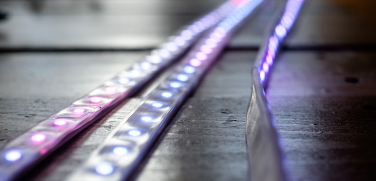
Combined with a light diffusion panel you end up with a beautiful glowy light show while you dance.
Project Breakdown
Cost: $180
Time: 6 Hours
Skill level: Advanced
What You Need
Arduino Uno
Standard A-B USB Cable
3 x LDP8806 LEDs (48 LED coil)
2.1mm female DC power adapter
Shifty Vu Shield
2x 5V 2A switching power supply (Purchase only one if you plan on supplying power to the Arduino from your PC)
3.5mm Male to 2x 3.5mm Female stereo splitter cable
2 x 3.5mm male to male stereo audio cable
Coloured wire
Wire stripper
Soldering iron/solder
Downloads
Note: For this guide I’ll be making an assumption you’ve programmed an Arduino before, or at least have a desire to learn. Check out The Absolute Beginner’s Guide to Arduino for an intro to get started.
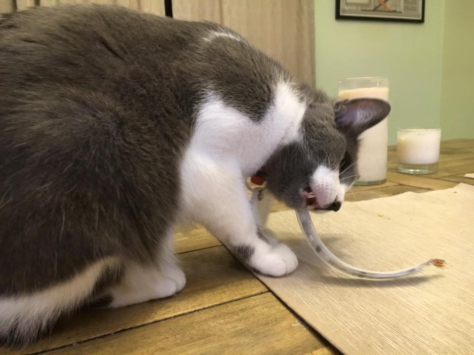
Protip: Don’t let the cat eat the LEDs
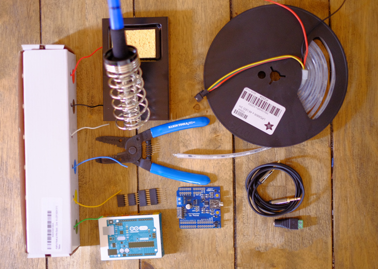
Setup
Get everything laid out on a decent sized working space. Plug in your soldering iron.
Step 0: Test your LEDs
The first thing you want to do is test your LEDs.
I quickly learned these lights don’t like to respond to power without data. If you jump ahead and try to test them with just power and they don’t work, chill out for a second. They might just need some code pumped through to activate the LEDs.
Before cutting the LED strip, follow this guide to connect the strip to the Arduino/power. Then run the sample code found here. Note: One end does have wires pre-soldered to it. Feel free to try with those. On the reel I received the pre-packaged wired just weren’t working (humbug) so I had to cut off two LEDs and start with a bare end of the reel.
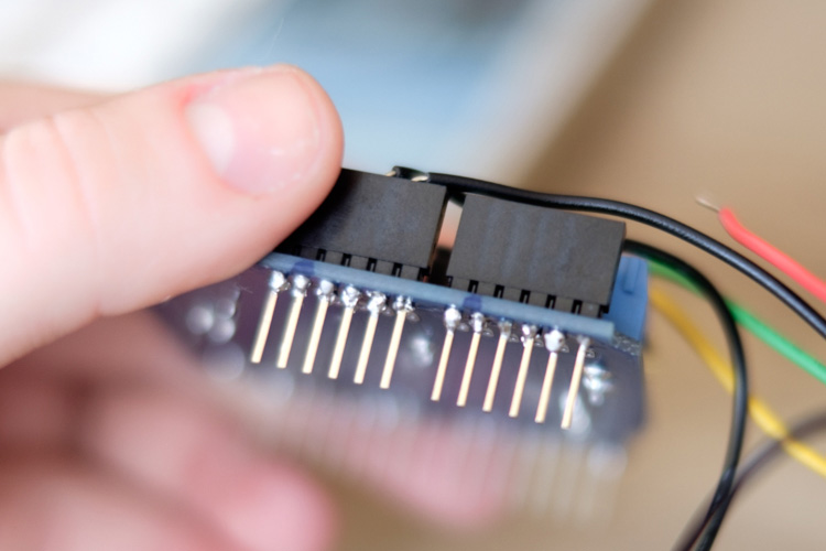
Step 1: Solder the VU shield
Grab the Shifty VU shield and the Arduino.
The VU shield comes with a set of header pins to connect to the Arduino. These need to be soldered as the connections are too loose to simply plug in even for testing purposes.
For tips on how to solder the shield to the Arduino, see this great guide from Sparkfun.
Step 2: Cut the LED strips
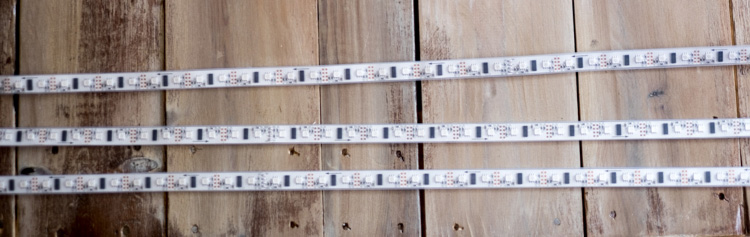
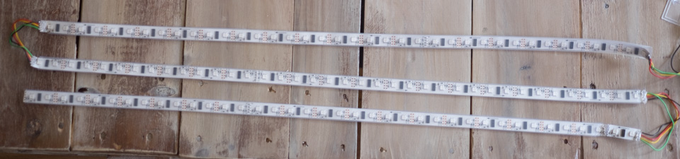
For this project I used 3 strips of 38 LEDs each. Note this will not work for a standard DDR cabinet monitor housing, as mine is custom built.
For this project you can decide how long you’d like the strips to be. Shorter strips (<10 LEDs) probably won’t give you a great effect, but decide what length works for your project and adjust the steps in this guide accordingly.
The LDP8806 strips come with two LEDs per segment, joined with solder every 16 LEDs. You can cut and connect at any point of the strip, however be sure to desolder if you need to disconnect the strip at a connection point. Check out this video which shows how to split this type of strip.
By now you should have something that looks like this.
Step 3: Prep for connecting
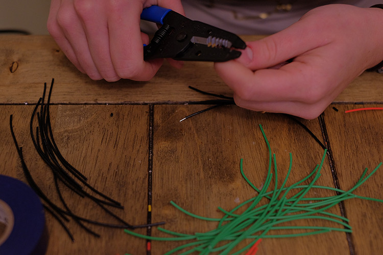
For this guide I’ll be using black, red, yellow and green wire. You can use whatever colours you want but keep in mind I’ll be referencing the colours in the following steps.
Strip the ends to get a few wires of each of the four colours.
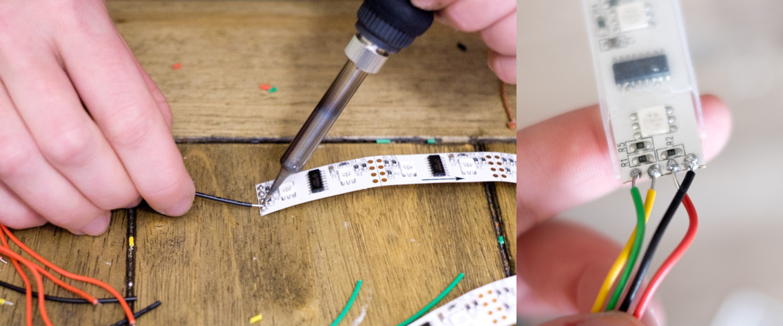
Grab your reel of LEDs. You want to find the end with the arrow pointing away from the cut of the strip. Depending on how they were shipped this can be at either end of the reel.
Carefully cut off the end of the weatherstripping so you can get to the connectors (or just cut it away altogether).
Tin the connectors with solder. This makes it way easier to solder the wires. Again, pay attention to the direction of the arrow; notice how it’s pointing away from the solder. This is the direction data flows, and if you mix them up you could damage the strip.
Just checking, you have the arrow the right way yeah? If not you’ll bust your strip. You’ve been warned.
Step 4: Connecting the LEDs
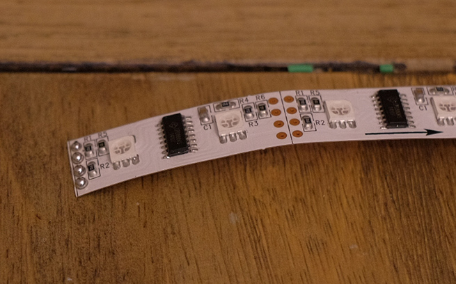
These LEDs have four pins; ground, 5v, C (clock) and D (data). Some sections of the strip have values marked on them, some don’t. That’s okay, just be aware of which pin you’re soldering to. Refer to the wiring diagram as you go and double-check the direction your strips are facing.
Solder the strips together, making sure each output connects to its respective input.
Once you’re done, you should have something like this.
Step 5: Connect to Arduino/power
Grab your 5V power supply and the Arduino.
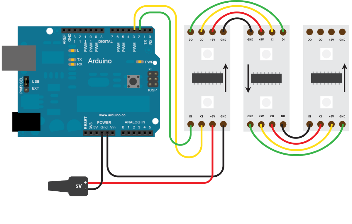
From the beginning input side of the strip arrangement, connect the green data wire to Pin 2, and the yellow clock wire to Pin 3. The red 5V wire connects directly to the power supply, and both the power and LED strip share a common ground with the Arduino.
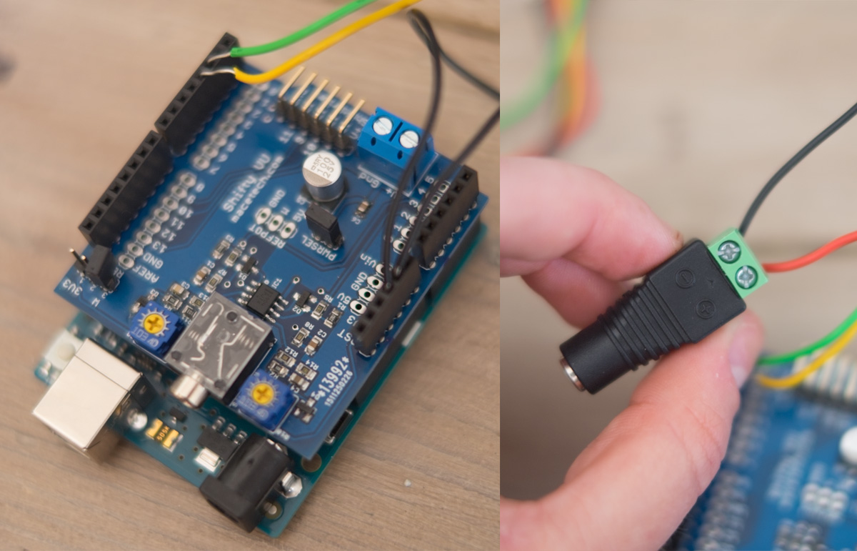
Refer to the wiring diagram above and double-check all connections.
Step 6: Code
Connect the Arduino to your PC. Grab your audio splitter and connect it to your PC. Use one audio cable to connect to the VU shield and the other to connect to a speaker. Connect the power adapter to a power outlet.
Once you have everything connected, run the test program from Step 0 to double-check everything lights up.
The fruits labour.
Download the project code from Github and add to your Arduino library. Open the Arduino IDE and upload.
Step 7: Get lit
Once everything is uploaded, play some music! You should now have something like this (mine is covered with a light panel sheet for diffusion).
0