Wiring Buttons with a JPAC or IPAC
If you’re looking to upgrade your arcade cabinet with extra buttons, the process is relatively straightforward if not a little… messy. Finagling the rats nest of wires found in older machines is the most difficult part of this project.
I decided to add two extra buttons to my cabinet to emulate the input of In The Groove dedicabs. DDR cabinets come with 3 panel buttons per player, while dedicabs come with 4.
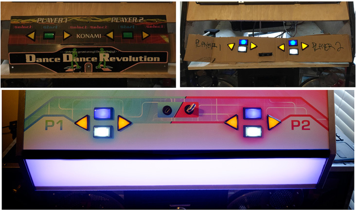
Before, during and after.
This guide will show you how to wire two extra buttons through a JPAC (or IPAC if you don’t have a JPAC), though can be repurposed for up to 10 buttons pretty much anywhere on your cabinet. You can also use the instruction here to rewire existing buttons if you need to.
This guide assumes you have functional, working lights with your cabinet. If you want to hook up a button without lights, skip Step 5. For information on controlling cabinet lights, see Controlling Cabinet Lights with LumenAR.
Note: The factory metal panel that comes with DDR cabinets clearly wasn’t designed to have a fourth button added to it, so you will have to find a solution to build a new panel or retrofit your existing one. Sometime in the future I may write a guide on this, but I’ll be assuming you have a place to put your new buttons. This guide will focus on the technical and wiring setup, though there are dimensions at the end of this post for creating a new plate.
Project Breakdown
Cost: $40+
Time: 1 Hour
Skill level: Advanced
What You Need
4x (or more) 22-18 AWG – .187″ Female Spade Terminal
4x (or more) 16-14 AWG – .250″ Female Spade Terminal
Crimping Tool (NOT pliers. If you use pliers you’re gonna have a bad time.)
Coloured Wire
Wire stripper
2x Arcade Buttons with LEDs (you can use any shape or colour for this)
IPAC (This is not needed if you own a JPAC)
Downloads
Note: You can try and repurpose the buttons on your existing plate, however these are glued on and may be difficult to dislodge. You’re likely better off buying a whole new set for about $25. You can find more pushbuttons here.
Step 1: Unplug
Turn your cabinet off and unplug the power.
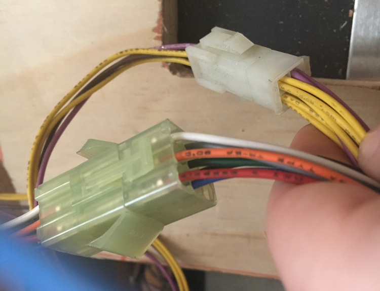
Open up the back of the cabinet and locate the two connectors for the front button panel. They should look something like the image below, though your wires may be different colours. Detach the connectors and go back around to the front.
Step 2: Detach the button plate
Remove the front button plate by unscrewing the screws around the edges and carefully remove it. Since you’ve unplugged the cables these should remove with the plate. Be careful with this step and move slowly as you don’t want to damage any wire that may be tangled.
Step 3: Remove the microswitches
Once you have the plate out, set it on a table.
Remove the microswitches by gently twisting them counterclockwise.
Remove all 6 of the microswitches from the plate and set the plate aside.
Step 4: Wiring the new buttons
There are two things you need to wire to get the buttons working. First is to wire the input connection which will run directly to your JPAC (or IPAC, I’ll get into that in a moment). The second is to daisy-chain the power from the existing switches to power the LEDs. If you don’t have LEDs or just don’t feel like wiring them up, you can still have a functional button without lights.
In the following steps, use this wiring diagram for reference.
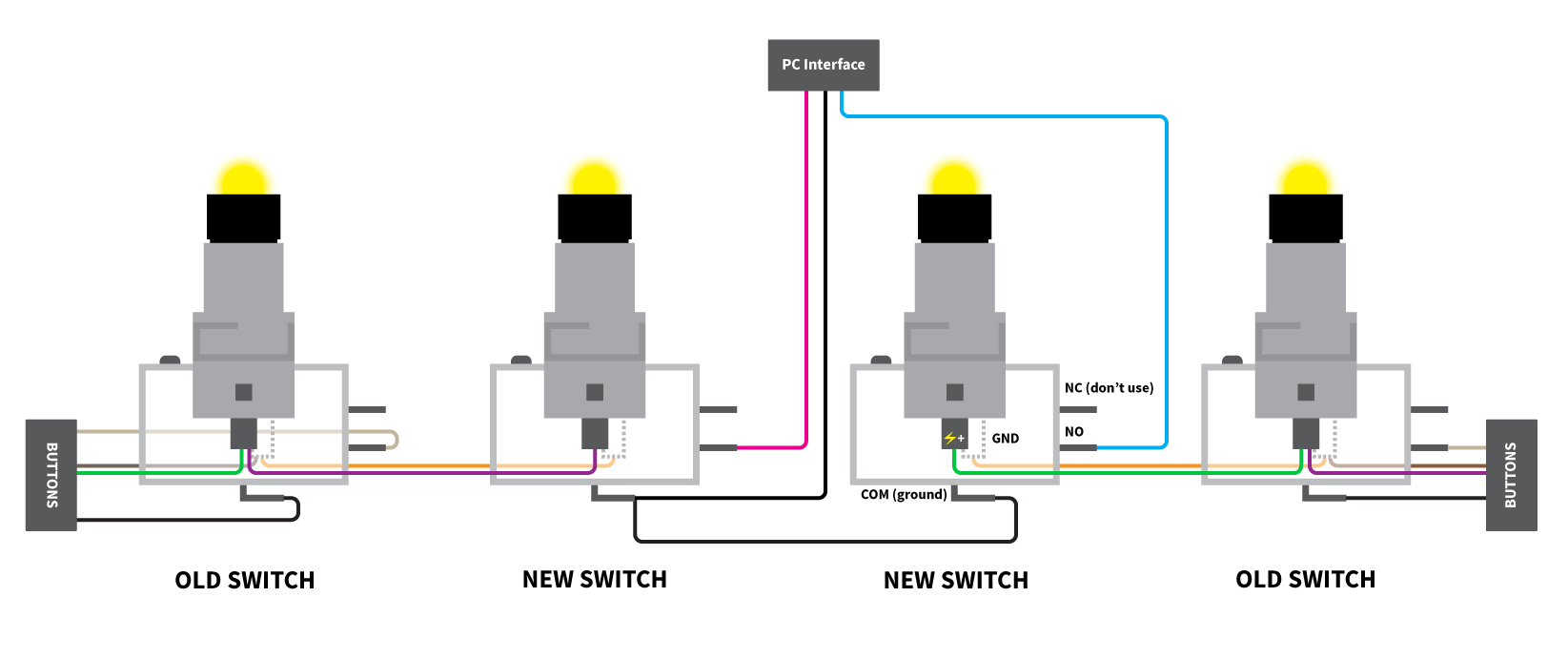
Wiring diagram. View in high resolution.
Before you begin, cut the following wires and strip the ends:
- 4x orange wires @ 3 in.
- 1x black wire @ 8 in.
- 1x black wire @ 4 ft.
- 1x blue wire @ 4 ft.
- 1x green wire @ 4 ft.
Note: You can use any colour you want, these are just the colours used throughout images.
Grab one of your new microswitches with LED and set it aside.
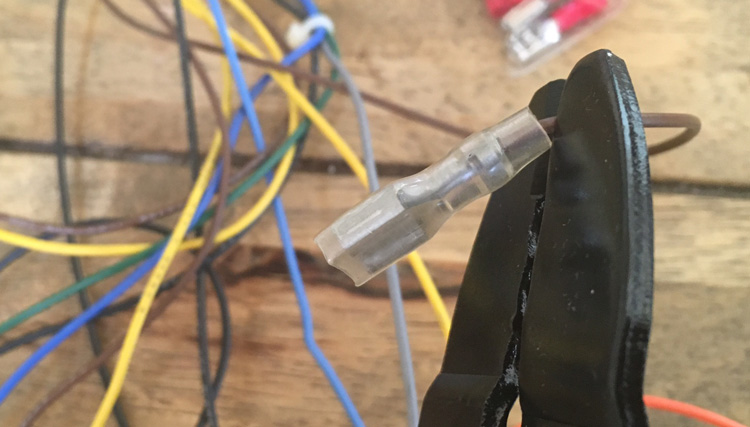
Grab two of your orange wires. Take two of the .250″ spade connectors and insert the wire, crimping the ends with your crimping tool. Attach a terminal to only one end of each wire.
Don’t let the wire run too far into the connector, you want it to stop just at the edge.
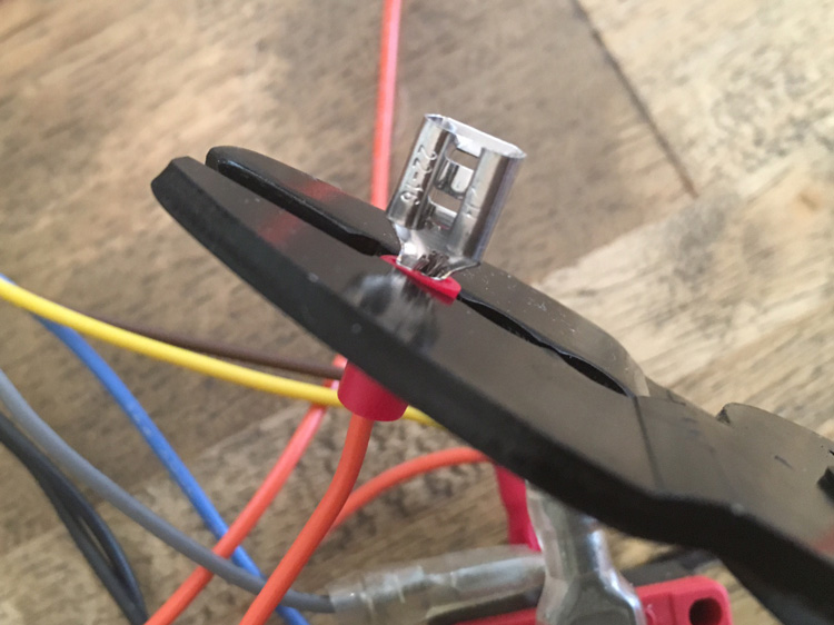
Protip: Make sure to use a crimping tool. If you use pliers you’re gonna have a bad time.
Next grab two of the .187″ spade terminals.
Take your blue wire and attach one end to the .187″ spade terminal. Next, take the two black wires and attach them to another .187″ terminal.
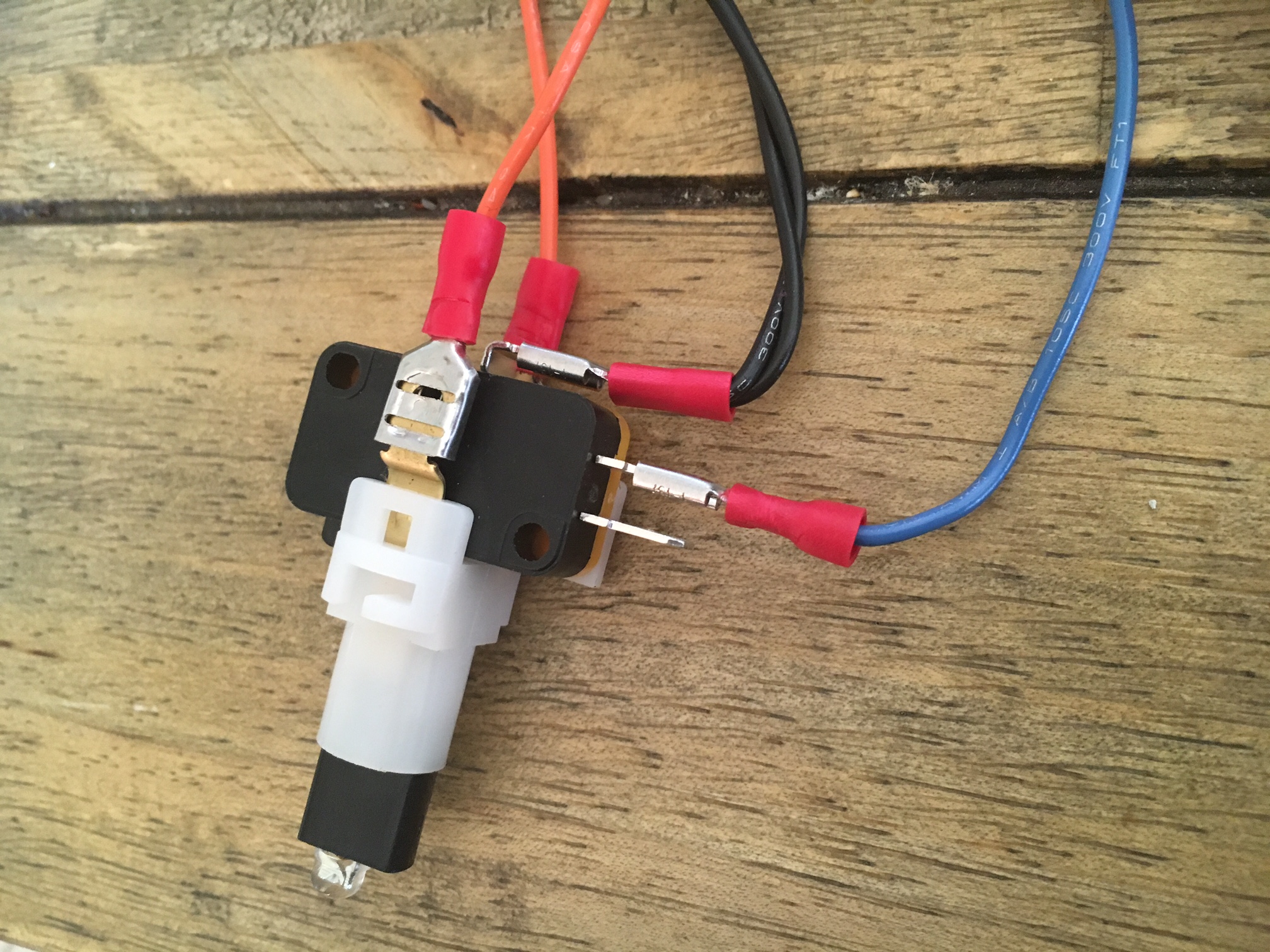
Attach the terminals to the microswitch. The .250″ terminals attach to the LEDs and the .187″ terminals attach to the switch.
By now you should have something that looks like this.
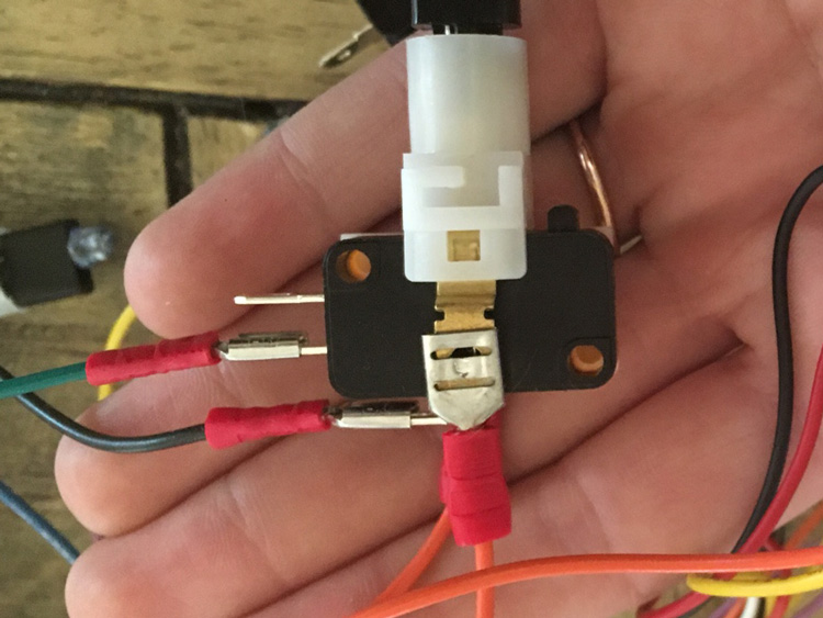
Repeat the above steps for the second microswitch, using the green wire instead of the blue. The following section will cover the ground (black) wire.
Take the other end of the 8 in. black wire from the first switch and connect it to the COM terminal on the second microswitch. Your second switch should look like this.
Step 5: Wiring the lights
Note: If you don’t have lights in your microswitch you can skip this step.
To get power to the LEDs, you’ll be daisy-chaining from an existing switch to run power to the new LED. The main benefit of chaining from the existing switches is the button lights will respond with the existing relay, which turns them on and off for the game. If you connect the LEDs to an alternate supply (which is doable) the lights will remain permanently on since they aren’t accessing the game data.
Pick two of the existing switches from the cabinet; one from the 1P side and one from the 2P side.
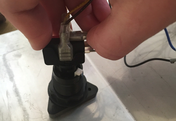
Remove the terminals which connect to the LED.
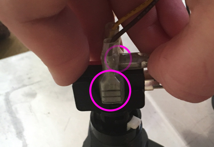
Take these off.
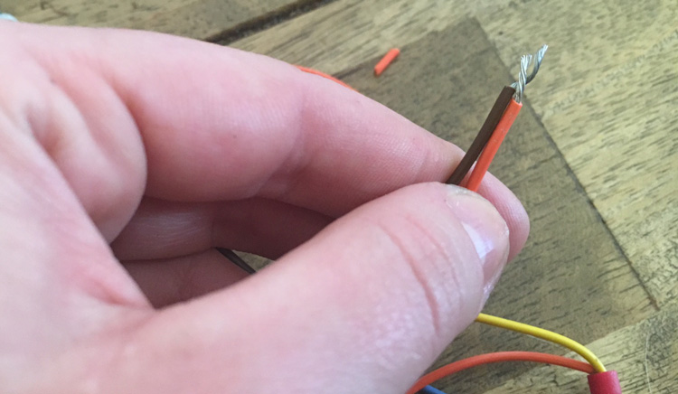
Using your wire cutters, cut off the existing terminal and strip the ends of the wire. This will be replaced shortly. Be sure to cut right at the end of the terminal, you don’t want to make this wire too short.
Repeat for each of the four wires.
Take the open end of the orange wire from your new microswitch. Twist this together with the stripped end of the wire from the existing switch.
Take your .250″ spade terminals and clamp to the end of the joined wires.
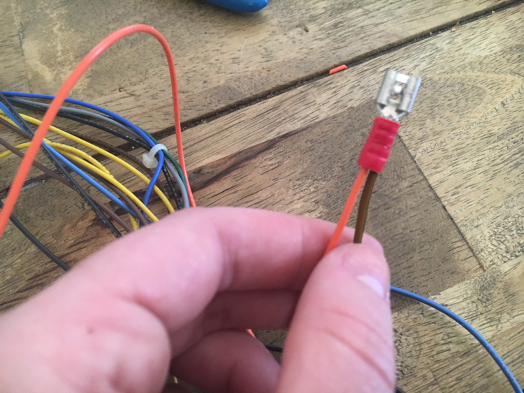
Repeat this for each connection from the two existing microswitches, joining 8 wires total (4 from the new switch and 4 from the old, 2 on each side).
The wiring should look like this for the 1P and 2P side switches.
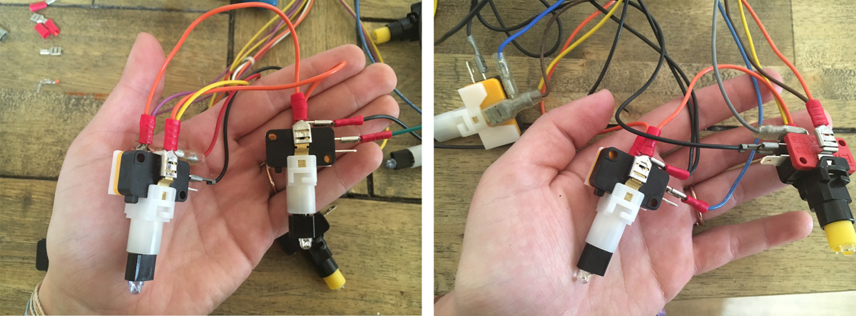
1P and 2P switches.
Step 6: Connect to your PC Interface
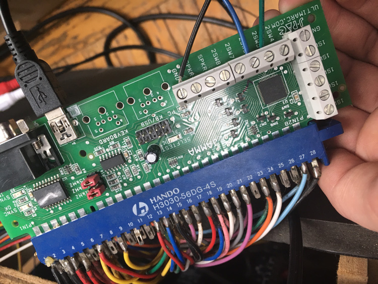
If you’re using a JPAC to interface between the JAMMA harness and the PC, you can use the additional pinouts on the JPAC to wire the buttons.
If you’re using something else which doesn’t have additional pinouts, such as a Minimaid, you can connect your wires using an IPAC and achieve the same result. Theoretically you could also try connecting with the additional pins directly on the JAMMA (25 and 26), though this didn’t work consistently for mine so your mileage may vary.
For JPAC
There are 10 additional pinouts which can be used for button connections on your JPAC. It doesn’t matter much which ones you use as long as they begin with “1S” or “2S”. The three extra pins are for speakers and grounding.
Grab a mini screwdriver and loosen the screw which holds the wire in place. Insert the stripped end of the coloured wire to two of the “S” pins.
Connect the black ground wire to the GND pin.
You should now have something that looks like this.
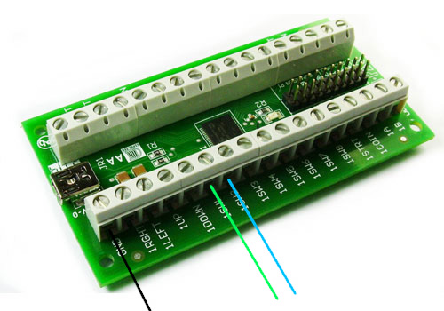
For IPAC
Wiring through an IPAC is similar though requires a separate board. Use this method if you’re not using a JPAC, or a board without additional pinouts (such as a Minimaid) to interface between the JAMMA and your PC.
Connect the green and blue wires to any of the “S” pins on the IPAC, and connect the black ground wire to the GND pinout.
Step 7: Connect the buttons
Turn your PC on and power up the cabinet. Your lights should illuminate in a glowly mess of crap.
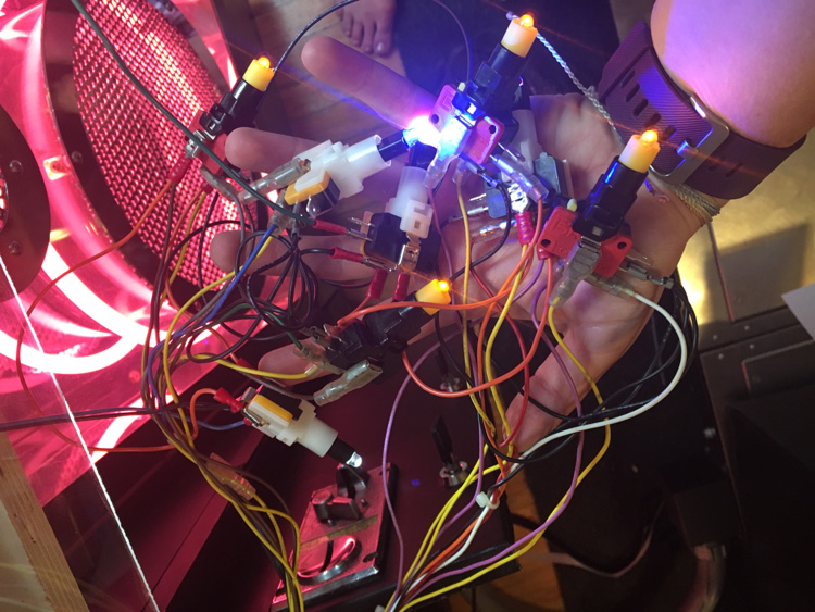
Somewhere an electrical engineer is rolling over in their grave.
If your cabinet doesn’t light up, the drivers may just keep the lights off until you load your game. If your new buttons don’t light up, take the bulb out and flip it around.
Connect your microswitches back to the buttons by gently screwing them in clockwise.
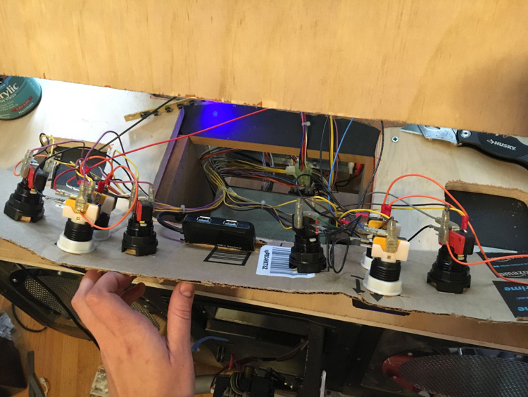
Ghettofabulous temporary button board.
Step 8: Configure the keys
Open Winipac to configure the keys for your new inputs. The screenshots are for a JPAC, but if you’re using an IPAC you’ll see something similar.
Click to select the pins you connected your wires to. Mine is using “P2 SW 5” and “P2 SW 6”. These are marked as “2SW5” and “2SW6” on the board.
Change the function to “Switch” and select the option for “Key”. From the Primary list, choose the button you’d like to correspond with the switch. I chose Num Lock and K as these don’t interfere with the Stepmania controls.
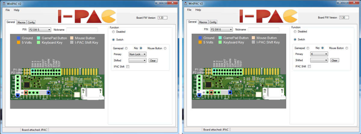
P1 and P2 settings
Close Winipac.
Step 8: Configure the game
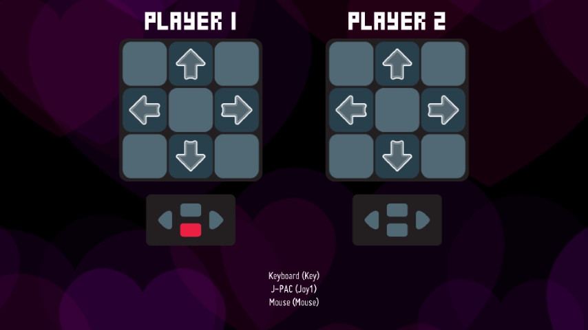
Launch your game and navigate to the keyboard mapping.
My buttons act as the “Select” button found on ITG cabinets. Map the “Select” function, or whatever function you’d like, to your new key.

Test your input in the “Test Input” screen to try out your new button. You should be good to go!
Building New Plates
You can try and patch-metal your existing plate and cut new holes for the buttons, or manufacture a new plate altogether by following the specs below.
Note: These dimensions are taken from a DDR Korean cabinet. If you have a different model your measurements will be different. Adjust accordingly.
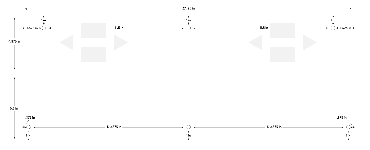
Button plate dimensions for a DDR Korean cabinet. View high resolution.
0